The circuits is very easy to understand.
D2 ensures Reverse polarity protection. With F1 being rated at 500ma to protect the rest of the circuit. D1 is a 5v1 zenor diode rated at 500mw which is purely there to prevent over voltage protection c4 decouples the 12F675 recommended in the data sheet as close as you can to pins 1 and 8 R2 to R5 limit the current through the Luxion Led which is switched on via the FET an 1RF540 biased off via R6
R6 and R7 form the biasing network via GP1 of the CPU turning on the Fet and of course the Luxion R1 and R10 form a potential divider for the switch which activates the timer sequence so that countdown can begin when this starts the Luxion Led is turned on at the end of the final countdown I.E 10 minutes then the Luxion LED is subsequently turned off Switch sensing is done via GP0 which is de bounced when finger press of the switch is released GPO looks for a logic High to start the timer sequence and is held low when no press is detected
The buzzer sound is sent via GP2, R9 which forward biases Q2 using a PWM waveform hence our sound of the buzzer.
Circuit DSN Files For Proteus
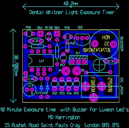
PCB layout Files For Proteus
Circuit Diagram In PDF Format
PCB layout Files in PDF Format
C Code for the 12F675


 Build yourself an inexpensive UV Timer light for tooth whitening. This little project could save you in the region of some £100 to £400 pounds It’s ideally for dental nurses who have to buy their own equipment.

