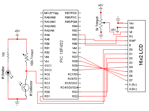
This is the standard 16x2 character LCD and the interface consists of 8 bits of data, with 3 control signals. Power, Ground and Contrast are the last signals to wire up. The PIC sends commands to this 16x2 LCD over the control and data lines and the LCD does what it is told. The HD44780 system that this LCD uses is standarized and the datasheet is widely available.The Theory
First, let me explain the overall theory of how the circuit and microcontroller will work to achieve our goal of building an rpm counter. The IR circuit will output pulses whenever it is interrupted (this type of IR circuit is also known as a 'photo-interruptor' circuit). The PIC microcontroller will stand by waiting to see the rising edge of one of these pulses.
Anytime a rising edge is detected the PIC will interrupt the current software and run a special subroutine to take note that the change on the signal occured. Now, if we keep track of how often that change occurs using a timer, we can estimate the instantaneous RPMs, making a digital tachomter!
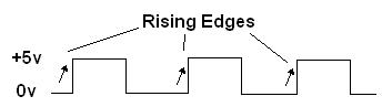
Output Signal From IR Circuit
The actual output signal from the photo-interruptor portion of the circuit will look similar to what you see above. The length of the +5 pulses are determined by how long the emitter and detector are interrupted.
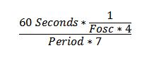
Calculate The RPMs: The Formula
If we know the period of time between photo-interrupts using the theory above, we can now estimate the current RPMs of the system. The forumla above, shows how. The Fosc is the current frequency of your system. I used a 4 MHz oscillator. Since the PIC takes 4 clock cycles to execute 1 instruction, we have to multiply it by 4. On the bottom, the reason we multiply the period between photo-interrupts by 7 is because the fan I'm using has 7 blades. Period*7 = 1 full rotation of the fan.