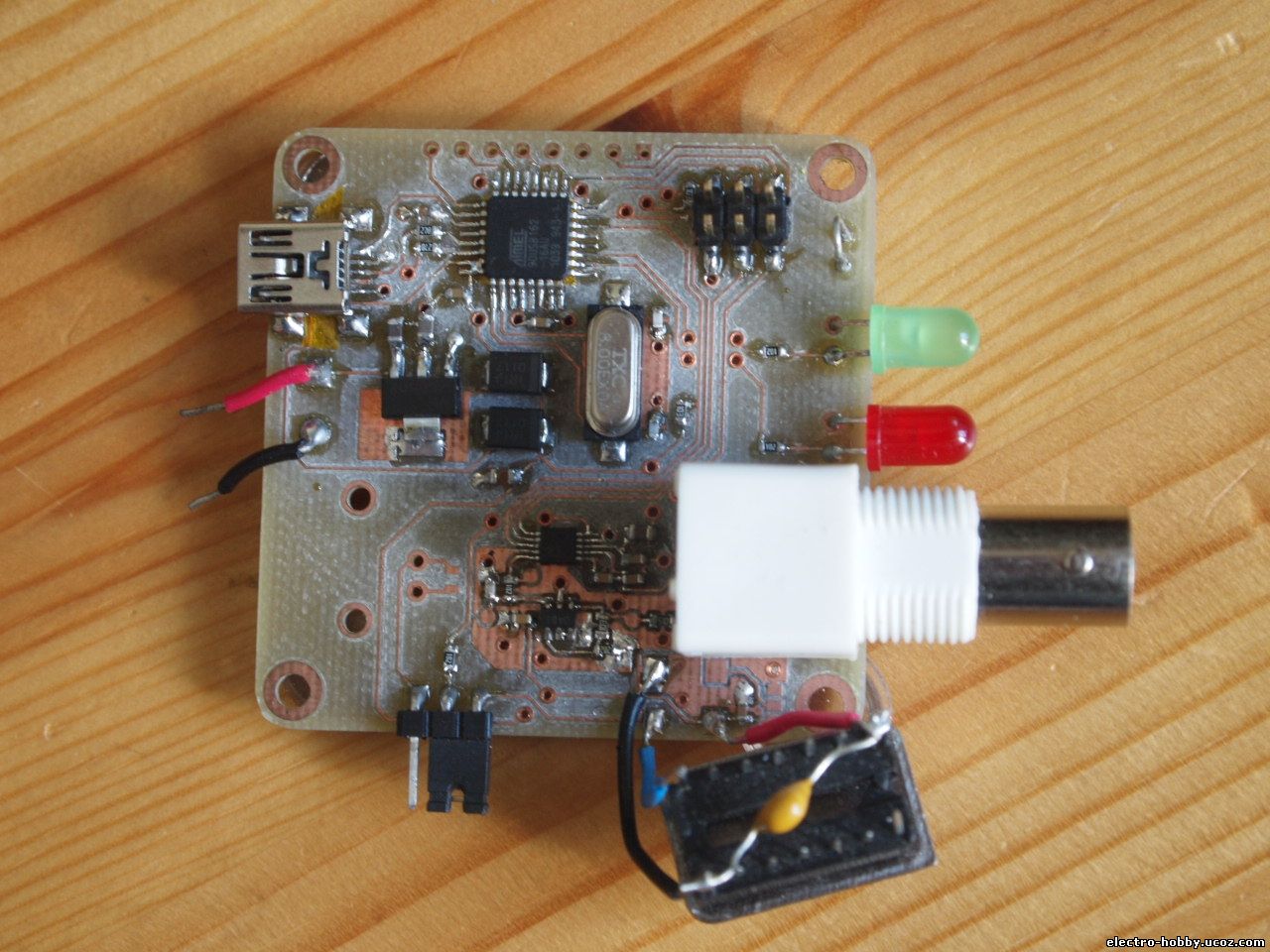
The parts
The integral part of this design is ofcourse the DDS chip, the AD9833 by Analog Devices. The chip has a 25MHz clock input, an internal phase locked loop, a sine lookup table and an ADC. By controlling it with it's SPI interface, you can make it output sine, triangle and square waveforms at frequencies ranging from 0.01Hz to 3MHz. It goes even higher, to ~7MHz, but the sine waveform starts to look pretty awful at that high frequencies.
To control that chip, I used an Atmel at90usb162, a cheap and small USB-enabled AVR microcontroller. It's going to provide a USB virtual serial interface to the computer and it's going to interpret the commands sent over that link and change the output of the DDS appropriately.
OPA357 is going to amplify the output of the DDS a little bit. The nominal output voltage of the AD9833 is 0.6Vpp, centered on 0.3v. The OPA357 was chosen because it supported the high frequencies required and it was available from texas instruments as a free sample.
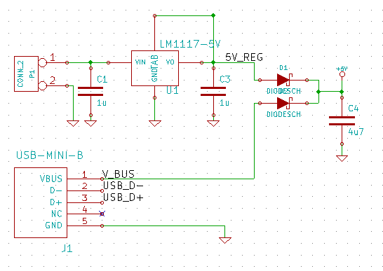
Schematic
The schematic and pcb were designed with KiCad, a pretty decent open source EDA. I'll just highlight some parts of the schematic here. The device can either be powered through the USB connection, or through a separate voltage input that gets regulated down to 5 volts. The two schottky diodes make sure the two aren't shorted together, if there's voltage coming in from both inputs.
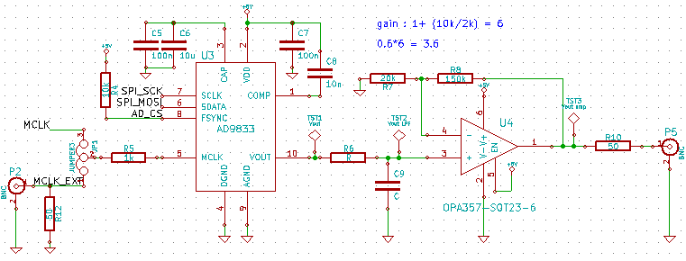
This is the circuitry around the AD9833 DDS. The bypass capacitors and their values are directly from the datasheet, as they should be. The clock source can be selected with the JP1 to be either an onboard oscillator, or an external clock source that is fed through a BNC connector. The output from the DDS is first lowpass filtered and then amplified. There's also a 50ohm resistor to allow for 50ohm termination. I've got test points scattered throughout the whole signal path to allow for easy testing.
PCB design
The PCB layout was pretty straight-forward. Here's a screenshot of the final PCB in 3d-view of KiCad.
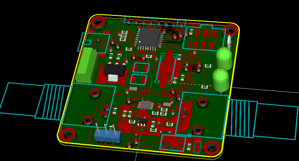
You can see the BNC connector for the external clock in that screenshot, that I haven't bothered soldering at least so far.
I designed the PCB to hold a surface mount oscillator, but didn't have one with the right output frequency. I did have the right oscillator in DIP package, so I just bodged it on the board like this:
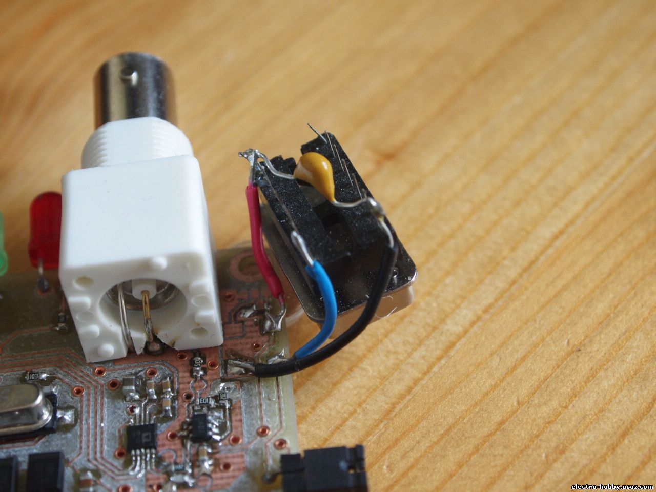
A bit ugly, but works just the same.
I also had a small error in the original design. The VUSB pin of the AVR should be connected to the supply voltage, not the USB VUSB. That way, if I power the device from external power without USB, the USB peripheral can still get power and can be initialized. A simple cut trace and a solder bridge was enough to fix that.
Protocol
So the board is connected to the computer via a virtual serial USB connection. There needs to be some sort of a standard way of communicating over it. So I wrote a simple standard before I got started on any code. I decided to use ASCII to enable a human to write the commands during testing and for easier debugging and code readability.
set commands:
sf1 [freq] #in Hz
sf2 [freq] #in Hz
sp1 [phase] #in degrees
sp2 [phase] #in degrees
sfo [1/2/m(modulation)] #frequency output
spo [1/2/m(modulation)] #phase output
so [o(off)/s(sine)/t(triangle)/q(square)] #output mode
sm [freq] #modulation freq
All commands ending with <carriage return><newline>
So for example, to set the output frequency 1 to 100Hz, you'd send "sf1 100 \r\n".
AVR code
The USB functionality was provided by the excellent LUFA USB library for AVRs. Then I reused some code I'd written before to handle the SPI and a relatively featureful library for the AD9833. Then some code to translate the commands sent over the serial to function calls to the ad9833 library.
PC software
The software is written in Python3. I started learning it a couple of months ago and have used it to create some simple UIs so far. I used the tkinter graphical framework for the GUI and pyserial for the serial connection. The code behind the UI isn't pretty, I'm still not that comfortable with Python. It's a fine language, but I prefer working with microcontrollers and writing code in c.
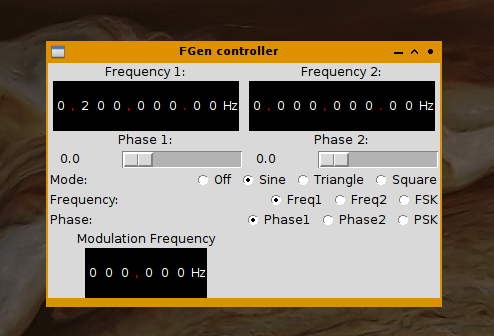
The UI turned out quite nicely in the end and it works well. There's some things I'd like to do differently, though. The modulation output selections should be in their own radio button collection, for example. If I wanted to add amplitude shift keying, there's no clean place to put it to. Maybe I'll get around to doing that at some point.
The logic behind the application is very simple: the application just sends appropriate commands over the virtual serial usb port whenever any of the values change on the UI. Not much to it.
All code and PCB files here