If you are a newbie and having the similar experience, here I suggest a general purpose I/O board that will not only reduce your prototyping time but also free up plenty of space on the breadboard for your project.
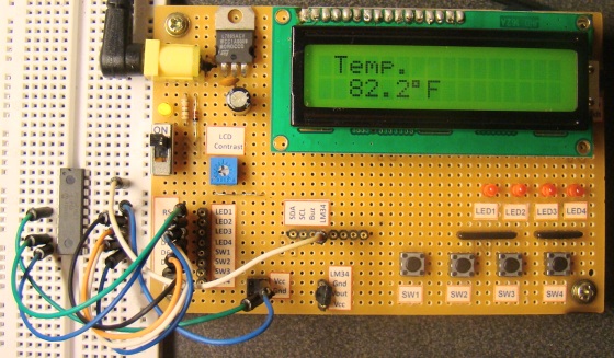
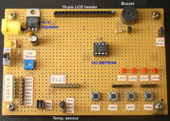
The construction of this board is very simple. You can solder basic I/O devices of your choice (that you use more frequently) on a general purpose perforated board and provide access to them through headers. The board that I constructed is shown below. It has got an LM7805 IC that provides a regulated +5 V power supply to rest of the devices on the board. A 16-pin female header is a plug-in for an HD44780-based alphanumeric LCD. The four data pins (D4-D7) and two control pins (Register Select, RS, and Enable, E) of the LCD are accessible through female headers, as shown on the bottom left part of the board. A potentiometer is also available on the board to adjust contrast of the display.
Four tact switches, four LEDs, and one coil buzzer serve as basic input and output devices. In this particular version, I have also added a LM34DZ temperature sensor device along with an I2C compatible serial EEPROM (24LC512). There’s plenty of prototyping space available for extending the functionality of the board in future.
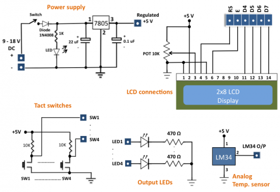
The circuit diagram of this project is very simple. There is nothing special as each component is independent and is not connected to any other component. The only common thing in them is all of them share the same Vcc and Gnd terminals. I have provided the following schematics for reference purpose.
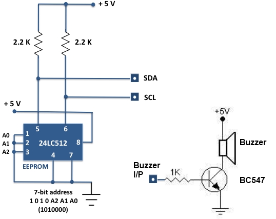
Circuit diagram of the I/O board I2C device and buzzer connections