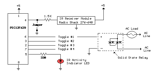
 The circuit above illustrates using the IR receiver module along control keys so the circuit will only toggle one of the 4 output with a PIC12F629 microcontroller to decode 5 individual IR remotes when a particular key is pressed.
The 5th key is assigned to the master clear function that toggles off the 4 outputs. Works with most hand held IR remote controls that send a single data stream. However, some remotes send multiple groups of data and only the first set of 40 bits or less will be recognized. This may result in the circuit responding to more than one key, or a single key may control more than one toggle switch. In most cases this problem can be resolved by selecting an alternate function on the remote such as (TV, DVD, SAT, AUX, Etc.). Circuit power supply is not critical and should operate on any voltage from 2 to 5 volts DC. I use a single 3.6 volt recharageable lithium battery such as found in cell phones.
Setup instructions to program the controller and record the desired keys.
Step 1 - Remove power and install a jumper wire from the input (pin 4) to ground.
Step 2 - Turn on 5 volt power to the circuit and the activity LED will flash 3 times and remain on.
Step 3 - Remove the jumper from pin 4 and the activity LED should flash three more times and remain on.
Step 4 - Press the desired keys in sequence to record the keys. The first key must be pressed twice to allow the program to establish the timing on the first press. So to program keys 1 to 5 you would press 1,1,2,3,4,5. At each keypress, the indicator should flash 3 times and remain on.
Step 5 - At this point, the indicator light should be out and you can test each key to verify it toggles the correct output. The data is stored in no-volitile EEPROM so when the circuit is re-booted without the jumper it should be ready to use with the existing programed data. For test purposes, you may want to install LEDs and resistors on the 4 outputs to verify correct operation.
----------------------- PIC12F629 HEX File ----------------------
:10000000000000008A0107309900850183169F01D6 :10001000C83085008312A501A901A701A201A70A82 :10002000FA30AA00453084001A30A000A30123084A :1000300083169B001C141A0883128000840AA30AEA :10004000A00B17281821851956285D308400193017 :10005000A00080018403A00B2928851D2D281821CC :1000600085193028851D322885193428B401851D4D :100070003728A50185194C282508031034020318D8 :1000800044282508B4003728250803102A02031C39 :100090004B282508AA004328A50A0821A51B51289A :1000A0003A282A08B407340CDE00A915C001C101A2 :1000B000C201C301C401A9191821A91D05112210EB :1000C0008519602805154030A91D7528A70DA718AA :1000D000453027194A30A7194F30271A5430A71A2C :1000E0005930271F7528A701A70AB40184000830DA :1000F000A600851D792885197B28A501851D7E28E8 :10010000851D882808210311A50A03199A2880282B :100110002830340603197D28B40A0310800D5E08C8 :100120002502031800140310A60B9928840A08302E :10013000A6007D280311A919E228B001A10105300C :10014000A0000530B0074030B10022103108AE00E9 :100150003007AF00D720B10AA00BA6282108B7208E :100160000630A1071E302106031D9F28E228221811 :10017000080082078518BE288514BF28851008004E :10018000051AC4280516C52805120800851ACA28AC :100190008516CB28851208000518D0280514D1280B :1001A00005100800851205128510051008002E089C :1001B00084000008B2002F08840000083206031DE6 :1001C000221408000D210D21A91D5628A71E56280E :1001D0001930A000A300A30A5E3084000008831633 :1001E0009A008312200883169B001C1555309D0031 :1001F000AA309D009C1483128C1FFC288C131C11A8 :100200008403A003A30BEE28A701A70AA90156287F :100210000F30A300A30B0A290800FF30A300132905 :10022000A30B13290800FF30A000A00B15291029EB :1002300005110D2105150D2105110D2105150D21A6 :0A02400005110D2105150D21080020 :02400E00043F6D :00000001FF
| 


