Parts list:
ICs:
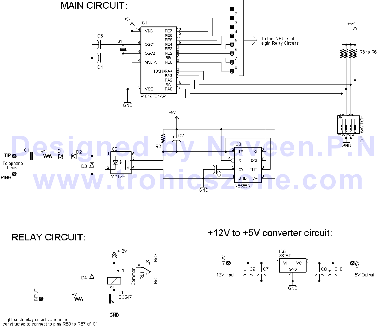
IC1- PIC16F84A microcontroller
IC2- MCT2E opto isolator
IC3- NE555 timer Ic
IC5- 7805C or 7805CT regulator IC
Resistors (all 1/4th W unless otherwise stated):
R1- 10K, 1W
R2- 15K
R3 to R6 - 2.2K
R7 - 2.2K (eight pieces for eight relay circuits)
Capacitors:
C1- 0.47uF/200V non electrolytic
C2- 47uF/25V electrolytic
C3,C4 - 22pF non electrolytic
C5- 0.01uF non electrolytic
C7,C8 - 0.1 uF non electrolytic
C9,C10- 100uF/25V electrolytic
Transistors:
BC547 - eight pieces
Relays:
12V, 60mA (or less) relay with 2A SPDT switching contacts - 8 pieces
DIP switch:
4 switch DIP
Diodes:
D1,D2 - 10V, 500mW zener diodes
D3 - 1N4007
D4 - 1N4007 (8 pieces for 8 relay circuits)
Crystal:
Q1 - 4MHz ceramic crystal resonator
Set the DIP SWITCH as follows:
Switch3 Switch4 No. of initial rings to Switch ON(activate half of the board)
OFF OFF 5
ON OFF 4
OFF ON 3
ON ON 2
The number of initial rings to Switch OFF is one more than the number of rings to switch ON. For example, if you have set switch3 OFF & Switch4 ON then number of initial rings to activate half of the board to switch ON the relays is 3 and number of initial rings to activate half of the board to switch OFF the relays is 3+1 = 4
Switch1 Swtich2 Delay before making the second set of rings
OFF OFF 20sec
ON OFF 15sec
OFF ON 10sec
ON ON 5sec
This is the maximum delay the board can take after it is half activated. It will reset after this delay.Now connect the circuit to the phone line and switch on its power supply.
You can test the board now. For example set the DIP switch to Switch1 ON, Switch2 OFF (15 sec delay) & switch3 ON, switch4 OFF (4 rings to activate half for switching ON). If you want to switch ON relay 1 (connected to RB0 of main circuit) then you have to do the following:
Give 4 rings and put down the receiver
Wait 5 seconds (this 5 seconds wait is required to prevent the board from detecting continous rings)
then within 15 seconds give 1 ring (1 ring for relay1, 2 rings for relay2 and so on) and put down the receiver
then within 5 sec the relay1 will switch ON
To switch off relay1:
Give 5 rings and put down the receiver
Wait 5 seconds (this 5 seconds wait is required to prevent the board from detecting continous rings)
then within 15 seconds give 1 ring (1 ring for relay1, 2 rings for relay2 and so on) and put down the receiver
then within 5 sec the relay1 will switch OFF
IMPORTANT: This circuit has been tested by me and found to work correctly. I cannot guarantee that the circuit will work at your end since it depends on error free construction and usage. Please do not contact for any support and requests, any such requests will not be entertained.
C-source code for pic