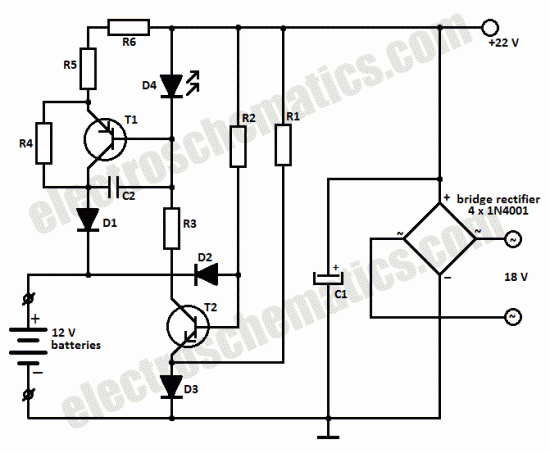
 This batteries charger circuit can be used to charge one or more batteries with the total nominal voltage of 12 V, meaning ten NiCd battery or six 2 V lead acid. The circuit is pretty small and can be built in a housing network adapter. The incorect usage is impossible: connecting the batteries with reverse polarity, shortcircuit of the output terminals or power loss have no impact on the charger or battery. This batteries charger circuit can be used to charge one or more batteries with the total nominal voltage of 12 V, meaning ten NiCd battery or six 2 V lead acid. The circuit is pretty small and can be built in a housing network adapter. The incorect usage is impossible: connecting the batteries with reverse polarity, shortcircuit of the output terminals or power loss have no impact on the charger or battery.
We can use a transformer with 18 V on the secondary and then using a diode bridge to rectify the 18V ac voltage we get 22V dc on C1.
The completely discharged batteries are charged at the begining with a 6 mA current thru R2-D2 and R4-R6-D1. One the bat. have reached 0.3 – 0.5 V, the base-emitter voltage of T1 is high enough to bring the transistor in conduction. Green LED D4 is used as an charging indicator and opens T1.
There is a 60 mA current flowing thru R5-R6, this means that the charging of a 500 mAh NiCd battery will take 12 hours. If the battery is connected with reversed polarity or there is a shortcircuit, the power transistor T1 remains blocked and the charging current can not exceed 6 – 12 mA. The current draw at maximum load is around 80 mA.
Components List
R1 = R2 = 10K
R3 = 1K
R4 = 5.6K
R5 = R6 = 12Ω C1 = 1nF
C2 = 220µF / 35V D1 = 1N4001
D2 = D3 = 1N4148
D4 = green LED T1 = BD140
T2 = BC546
| 


