| Statistics |
Total online: 1 Guests: 1 Users: 0 |
|
 | |  |
| | Home » Audio » 45 Watts Audio Power Amplifier Using HEXFET Technology
13:33 45 Watts Audio Power Amplifier Using HEXFET Technology |
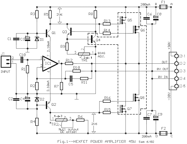
The circuit was based on HEXFET technology to create a power amplifier that would produce an output power of 45 Watts.

- LF351 – a wide bandwidth single JFET operational amplifier with high slew rate, operation without latch up, compensated internal frequency, high input impedance JFET input stage, protection for output short circuit, low offset current and input bias, wide common-mode and differential voltage range, low power consumption, and adjustable internal input voltage
- IRF9540 – a fifth generation HEXFET from International Rectifier that utilizes advanced processing techniques to achieve extremely low on-resistance per silicon area combined with the fast switching speed and ruggedized device design that HEXFET power MOSFETs are well known for, and provides the designer with an extremely efficient and reliable device for use in a wide variety of applications due to its fully avalanche rating, 175ºC operating temperature, and dynamic dv/dt rating
The circuit can perform the preamplifier and the driver support using the op-amp IC1. The gates of the FETs are being driven by the voltage drop across the resistors R5 and TR2/R6, which is proportional to the level of the input signal. The voltage is stabilized in the supply lines by the transistors Q1-2 which will also ensure the proper voltage drop to be supplied across IC1 that should not exceed 18 V. The current consumption of the ICs that can replace IC1 should be 2 mA which signifies the voltage drop across R5 and TR2/R6 equivalent to 2.4 V up to 2.6 V. The current is being regulated by the transistors Q3-4 while the adjustment of biasing comes from the trimmer TR1. The trimmer TR2 provides the lessening of DC offset voltage in the output of the amplifier. The value that was initially regulated causes the amplifier to have a total resistance from R5 equal to TR2 and R6. If the minimization of DC offset voltage does not provide big difference and if the value of R6 and replace R5, TR2 can be suppressed from its operation. The thermic stability of the amplifier is being considered by placing Q4 into a heatsink to reduce the essential feedback and ensure the stability of biasing. This is due to the positive thermic factor from a small current that increases the temperature of Q5-6 which corresponds to the temperature increase of Q4. The thermic factor of the FET will become negative during a larger current of the amplifier. During the regulation of TR1, it takes 2 V of voltage drop across the resistors if the resistors do not overheat. The power supply of the circuit contains supply stages such as the power output stage, control stage, preamplifier supply, and protection stage.
The 45 W power amplifiers are best applied in car radios and CD/MD players for boosting audio signals and as voltage regulator. |
|
Category: Audio |
Views: 2971 |
|
| |
 | |  |
|
|
| |


