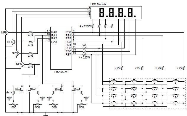
Simple 4-channel digital voltmeter with LED-display and keyboard . This digital voltmeter is based on PIC16C71 (Microchip). The PIC16C71 device’s I/O ports have an improved sink/source specification. Each I/O pin can sink up to 25 mA and source 20 mA. In addition, total PORTB source current is 100 mA and sink current is 150 mA.
PORTA is rated for a 50 mA source current and 80 mA sink current. This makes the PIC16C71 ideal for driving 7-segment LEDs. Since the total number of I/O pins is limited to 13, the 8-bit PORTB is used to drive the 4 LEDs, while external sink transistors, or MOSFETs.
The multiplexing is achieved by turning on each LED for a 5 ms duration every 20 ms. This gives an update rate of 50 Hz, which is quite acceptable to the human eye as a steady display. The 5 ms time base is generated by dividing the 4.096 MHz oscillator clock. The internal prescaler is configured to be a divide by 32 and assigned to Timer0. TMR0 is preloaded with a value = 96. TMR0 will increment to FFh and then roll over to 00h after a period = (256 – 96) • (32 • 4/4096000) = 5 ms.
When TMR0 rolls over, the T0IF flag bit is set, and because bits T0IE and GIE are enabled, an interrupt is generated.A 4x4 keypad can very easily be interfaced to the PIC16C71 device’s PORTB .
The internal pull-ups have a value of 20k at 5V (typical). In order to sense a low level at the input, the switch is "connected” to ground through a 2.2 kΩ resistor. A key hit normally lasts anywhere from 50 ms to as long as a person holds the key down. In order not to miss any key hits, the keypad is sampled every 20 ms (just after the update of the MSD).
The software implements a simple timer which increments at a 1-second rate. Every second, the 4 nibbles (two 8-bit registers, MsdTime and LsdTime) are incremented in a BCD format.
The analog channels are connected through individual potentiometers to their respective analog inputs and are sampled every 20 ms in a round robin fashion. The sampling rate can be increased to as fast as once every 5 ms if required. The keypad sampling need not be any faster than once every 20 ms.
This project and source code was designed by Stan D’Souza from Microchip Technology.
|