This was actually the first time I ever needed to multiplex analog channels so it was a good opportunity to learn how to use them. My task was to measure the temperature of 32 thermistors (NTC) with a microcontroller and later process that data. Obviously you cant find that much analog input channels on your common microcontroller so you need to multiplex the signals. First I looked for large analog multiplexers with 16 input channels but those are way too expensive. As it turns out its cheaper to use more smaller 8ch multiplexers(example Digikey pricing: 2pcs 16:1 mux from TI is $7.84 while 3pcs of 8:1 mux from TI is $1.53). I was able to get the 74HC4051 at a good price so I started creating the design around it.
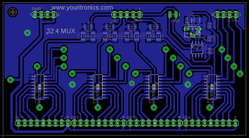
With just four 74HC4051 I can multiplex 32 input channels to 4 outputs. The 74HC4051 has 3 select lines A,B,C and one enable line E. These 4 lines are used for control and they can be tied together like I did for controlling all 4 chips with the same 4 lines. By a combination of state (high/low) for A,B and C you can control which input gets connected to the output. In the schematic you will also find a table with the address select concerning the 3 pins A,B and C. The enable pin is used to disconnect all internal switches (when high) or allow connection (when low) by selecting the appropriate address. Each 74HC4051 got its own 0.1uF decoupling cap close to its supply pins and if you’re design is very sensitive to noise you can further optimize the layout and place more filtering on the supply lines.
To get a more stable reading at the output of the thermistor(actually at the output of the multiplexer) I also placed a low pass filter which later on after assembling and testing turned out to be unnecessary even creating problems because I was switching the lines faster than it took the filter to settle so I left the filter components out during assembly.
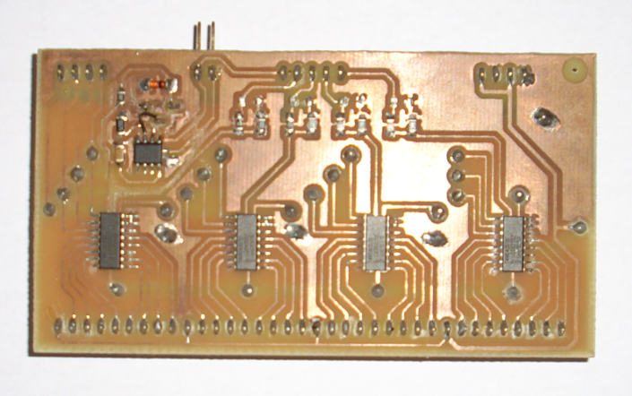
The PCB was manufactured at home hence the big vias and it was designed to allow a second board with the microcontroller to be stacked on top of it. Everything was tested on an Arduino and it works perfectly. The schematics and board file are released under CC-BY-SA and can be downloaded from the link bellow.