| Statistics |
Total online: 1 Guests: 1 Users: 0 |
|
 | |  |
| | Home » Repair PC's components » Computer Chassis front audio wiring
14:26 Computer Chassis front audio wiring |
AUDIO 10-pin design can be applied to high-end chassis, with amplifier and speakers can also be applied to a common chassis front headset jack.
1, AUD_MIC the front panel microphone input
2, AUD_GND analog audio circuitry land line
3, AUD_MIC_BIAS microphone power supply
4, AUD_VCC analog audio circuit, the +5 V power supply filtering
Of, AUD_FPOUT_R front panel and right channel audio signal
6, panel right channel audio signal return AUD_RET_R
7, HP_ON reserved for future headphone amplifier
Empty, the KEY pin
9, AUD_FPOUT_L front panel of the left channel audio signals
10, AUD_RET_L front panel and right channel audio signal
AUDIO 10-pin design can be applied to high-end chassis, with amplifier and speakers can also be applied to a common chassis front headset jack. 4 pin is used to the power amplifier to provide +5 V power supply, so do not put any line connected to the 4-pin, otherwise it will burn the motherboard and headset front headset jack to connect the common chassis.
If you do not use the front audio jack, pins 5 & 6, 9 & 10 must be jumpered so that the output signal will go to the back of the audio ports. Otherwise, the back of the Line-Out audio interface will not work.
Types of chassis front headset jack and connection:
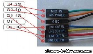
I / O panel, basic Intel? Connect the standard design, the 7 cable:
Front audio jack, headphone jack with spring switches, multi-connection (LINE OUT RL LINE OUT RR) for the two left and right channels to return to the motherboard. This headphone jack of the chassis, the back of the audio output jack for connecting the speakers, front jack for connecting headphones. When using the front jack to connect headphones, automatically disconnect the back of the speakers, unplug the headset automatically when connected to the speaker.
7 of the front line with the motherboard audio interface JAUD1 connection as follows:
Microphone input (MIC IN) --------> ①
Ground (GND) ------------> ② The
Mike power (MIC POWER) ------> ③
Panel right channel output (LINE OUT FR) of ----> ⑤ The
Panel right channel return (LINE OUT RR) for ----> ⑥ The
Panel, the left channel output (LINE OUT FL) ----> ⑨
The panel left channel return (LINE OUT RL) ----> ⑩
|
|
Category: Repair PC's components |
Views: 1081 |
|
| |
 | |  |
|
|
| |