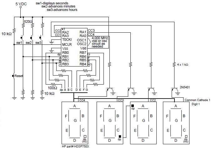
Digital clock project based on the PIC16C54 microcontroller can be designed using the following circuit diagram . This digital clock electronic project based on the PIC16C54 is a simple time-of-day clock incorporating four seven-segment LED displays and three input switches. There is also an additional reset switch that would not normally be incorporated into the final design. The common cathode for each display is turned on with transistors connected to the four I/O lines of PORTA . A low output turns on the PNP transistor for the selected display. The PORTB pins activate the LED segments. The PORTB pins activate the LED segments. The switches are also connected to PORTB I/O pins. When no buttons are pressed, the circuit will display the current time, starting at 12:00 on reset. Pressing SW1 will cause seconds to be displayed. The time is set by pressing SW2 to advance minutes, and SW3 to advance hours . The displays used were common cathode and turned on with transistors to avoid trying to sink too much current into the PIC16C5X. 100 W resistors were used in series with the segments to obtain the desired brightness. Different values may be required if different displays are used.
All of the same display segments are linked together (A-A-A-A, B-B-B-B, etc.) and are individually selected by turning on only the desired display. This simple digital clock project based on the PIC16C54 microcontroller must be powered from a simple 5 volt DC power supply circuit . This digital clock project based on the PIC16C54 microcontroller ( circuit and software ) was designed by Dan Matthews Microchip Technology Inc . |