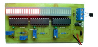
9V battery can be used for voltage supply. In this situation, circuit operates properly until voltage of the battery decreases to 4V. Current consumption depends on the number of litLEDs. Every led draws about 5mA, at about 18° 16 LEDs will be lit and total LED current draw will reach to 80mA. If the circuit left operating, battery will discharge in a short time. To prevent this situation, circuit should be opened only when needed. So putting a on-off switch will be sufficient. If a 9V AC/DC adaptor is used, circuit can be left operating continuously with no drawback.
Last step is placing the board into a proper box.If it is put in a box, temperature sensor should be placed outside. You can draw a scale divided in to 2.5mm parts. If you put a piece of glass or plexy on the led bargraphs, they will be more visible.
To test the circuit, you can use a mercury thermometer as shown in the image. We can see our thermometer gives right results.
Electronic_Thermometer.rar


 As shown in the schematic, temperature sensor of our electronic thermometer is LM35DZ. There are some kinds of LM35 IC, since it is cheap and easy to find we used LM35DZ in our project. It measures from 0°C to 100°C with a very linear output graph.For one degree change, it increases its output 10mV.