- Graphic Equalizer – a common type of equalizer considered as a high-fidelity audio control which consists of a bank of sliders for cutting and boosting different frequency ranges or bands of sound and allows the user to see graphically and control individually a number of different frequency bands in a stereophonic system
- TL074 – low noise JFET quad operational amplifier with features such as high slew rate, latch up free operation, compensated internal frequency, low harmonic distortion, protection from output short circuit, JFET input stage with high input impedance, low offset current and input bias, low noise, and wide common-mode and differential voltage range
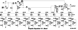
The graphic equalizer is one common type of equalizer which is made up of a collection of sliders, formed by potentiometers, for boosting and cutting off different frequency ranges or bands of an audio signal. It allows an individual to see the high fidelity audio control in a graphical way and the control is made possible on different bands especially in a stereophonic system. Graphic equalizers are typically made of several audio filters wherein the quantity and width of filters depends on application. The audio filters are centered at a specific frequency in the audio range.
In sound production, this circuit can be used essentially where the characteristics in spacing of frequencies can be heard. The only concern is that this could be a problem in some area pertaining to the gain, if it goes too far. The circuit is being divided into two sections, having one for each channel and the potentiometers which act as the faders. These slide potentiometers are responsible for controlling the gain or volume in most graphic equalizers by moving a control button up or down. Normally, the gain is increased with upward movement of button.
In each channel, the slide potentiometers are in side-by-side position where the left side holds the lowest frequency while the right side has the highest frequency. A graphical curve will be created by doing this position of buttons as it represents the gain as a function of frequency for every channel. The presence of switch S1 is for the purpose of bypassing the circuit without any alteration in the frequency, which will settle down the musical program in a flat response. Each channel is being regulated by the potentiometers RVs. The circuit is being supplied by a 15 V source with a current of 300 mA.
The use of graphic equalizers is practically found in all professional recording studios and professional live sound reinforcement where they are using 25 to 31 frequency bands, which is necessary to be able to control the feedback tones and room modes in an easier way. In consumer use, the graphic equalizers are being used in middle and high end stereophonic sound systems while in personal computers, they are utilized for fine tuning of sounds with the use of graphic equalizer programs like the one embedded with Windows Media Player program.