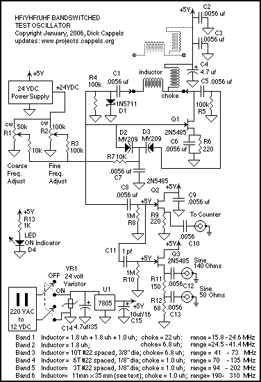
This test oscillator covers 16 MHz to 300 MHz in six bands, using varactor tuning. It has a high level output to drive a frequency meter and two sine wave outputs, one of which is 50 Ohms.
The time came, when I needed a simple test oscillator that covers a wide range of frequencies. My main interest at the time is the 100 MHz to 300 MHz region, but since it wasn't much trouble to extend the coverage to under 20 MHz, I did so.
The circuit is a modified Colpitts oscillator, tuned with MV209 varactor diodes. The resonating inductor and the drain choke are selected by a rotary switch. 1N5711 Schottky diode, D, clamps the maximum positive voltage on the gate of oscillator FET, Q1 to just above ground to reduce the distortion in the wave form on the gate of Q1. Buffer Q2 provides about 1.8 volts peak-to-peak at 20 MHz to drive a frequency meter.
 Since the P-P voltage on the gate of Q1 is too large to be buffered by a 2N5485 without sever distortion -see the pictures further down this page), the signal is reduced by a capactitive voltage divider formed by 1 picofarad capacitor C11 and the input capacitance of Q3. This results in about 650 millivolts on the gate of Q3, and about the same on the source.
To make a 50 Ohm output, so the generator can drive a 50 Ohm cable, I measured the output impedance of Q3 while using a 220 Ohm source resistor. This was done by measuring the Peak-to-peak output voltage without a substantial load, at 20 MHz, then loading the source with an additional 470 Ohm resistor, and calculating the effective output resistance of the source follower based on the change in amplitude. This value was found to be about 139 Ohms. This is much simpler and more direct than trying to calculate the output impedance as a function of data sheet values, since the key parameters such as IDon vary too widely to allow design without trimming. The output impedance is about 50 Ohms at 20 MHz, but this design approach does not separate out the resistive from the reactive part of the impedance, and I expect the impedance to change as a function of frequency.
Using a program that seeks numerical solutions to formulae, I found the values of resistors for R11 and R12 that simultaneously satisfy the requirement that the total resistance be equal to 220 Ohms and the resistance from the the connection between R11 and R12 to ground, including the effects of the source follower, is equal to 50 Ohms. The values, R11 = 150 Ohms and R12 = 68 Ohms are the closest 5% resistor values.
The +24 volt power supply was made separately, and is described separately on this site.
|


