
| Statistics |
Total online: 1 Guests: 1 Users: 0 |
|
 | |  |
| | Home » Tests and Measurement » LC meter with pic16f628a
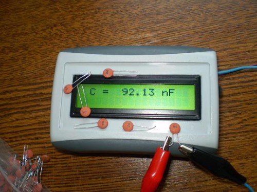
22:40 LC meter with pic16f628a |
This LC meter design is pretty old but since it is a perfectly good device there was no need to design/build/debug one of my own. So, I just changed the original firmware a bit and added few electronic goodies to it to make it more compact.
  Calibration: - Check that you have put all the components in the right places.
- Check that you have soldered every lead.
- Double check the PIC orientation, the diode and the 7805.
- Don't forget - the PIC (as purchased) isn't programmed. You gotta load the LC Meter code into it before it will work.
- Apply power carefully. If possible, use a variable regulated supply for the first try. Measure the supply current while gradually increasing the voltage. The current should be below 20mA. The prototype drew just 8mA. If you see nothing on the display and everything else checks out OK, try adjusting the Contrast trimpot. If it is set too far off, you will see nothing. The display should briefly show the word Calibrating, then C=0.0pF (or some other capacitance up to +/- 10pF ).
- Allow several minutes "warm-up", then press the "zero" button to force a re-calibration. The display should now show C=0.0pF.
- Connect your "standard" capacitor. The LC meter should read somewhere near its value (with up to +/- 10% error).
- To raise the indicated capacitance, join the links marked "4" on the diagram below. To lower the indicated capacitance, join the links marked "3" on the diagram below. When the indicated value is "close enough" to the standard, remove the link. The PIC will remember the calibration. You can repeat this as many times as you like (up to 10,000,000 times I think before you wear out the PIC).
- If the meter misbehaves, you can use the links "1" & "2" to check the oscillator frequency. Apply link "2" to check the free running frequency "F1" of the oscillator. This should be shown as 00050000 +/- 10%. If this reading is too high (near 00065535), the meter may go into "numerical overflow" and give you an error message. If the reading is too low (say below 00040000), you will lose some accuracy. Apply link "1" to check the "calibration" frequency "F2". This should be near 71% +/- 5% of the "F1" reading that you get by applying link "2".
- Experts may like to adjust the inductor value to raise F1 to near 00060000 to obtain maximum resolution from the meter. An "L" value of 82uH is preferred instead of the specified 100uH (but you can't buy 82uH inductors in Bendigo).
- If the meter shows near 00000000 for F1 and or F2, then recheck the wiring around the L/C switch, 'cos it sounds like your oscillator has stopped. - The Inductance measuring function is automatically calibrated when you calibrate the capacitance function. All the testing required is to check that the meter can be "zeroed" with the terminals shorted together. Download Source Code
|
|
Category: Tests and Measurement |
Views: 5011 |
|
| |
 | |  |
|
|
| |


