First of all let us consider a few basics in building electronic circuits on a printed circuit board. The board is made of a thin insulating material clad with a thin layer of conductive copper that is shaped in such a way as to form the necessary conductors between the various components of the circuit. The use of a properly designed printed circuit board is very desirable as it speeds construction up
considerably and reduces the possibility of making errors. Smart Kit boards also come pre-drilled and with the outline of the components and their identification printed on the component side to make construction easier.
To protect the board during storage from oxidation and assure it gets to you in perfect condition the copper is tinned during manufacturing and covered with a special varnish that protects it from getting oxidised and makes soldering easier.
Soldering the components to the board is the only way to build your circuit and from the way you do it depends greatly your success or failure. This work is not very difficult and if you stick to a few rules you should have no problems. The soldering iron that you use must be light and its power should not exceed the 25 Watts. The tip should be fine and must be kept clean at all times. For this purpose come very handy specially made sponges that are kept wet and from time to time you can wipe the hot tip on them to remove all the residues that tend to accumulate on it. DO NOT file or sandpaper a dirty or worn out tip. If the tip can not be cleaned, replace it. There are many different types of solder in the market and you should choose a good quality one that contains the necessary flux in its core, to assure a perfect joint every time. DO NOT use soldering flux apart from that which is already included in your solder. Too much flux can cause many problems and is one of the main causes of circuit malfunction. If nevertheless you have to use extra flux, as it is the case when you have to tin copper wires, clean it very thoroughly after you finish your work. In order to solder a component correctly you should do the following: Clean the component leads with a small piece of emery paper - Bend them at the correct distance from the component body and insert the component in its place on the board. You may sometimes find a component with heavier gauge leads than usual, that are too thick to enter in the holes of the p.c. board. In this case use a mini drill to increase the diameter of the holes slightly. Do not make the holes too large as this is going to make soldering difficult afterwards.
Take the hot iron and place its tip on the component lead while holding the end of the solder wire at the point where the lead merges from the board. The iron tip must touch the lead slightly above the p.c. board. When the solder starts to melt and flow wait till it covers evenly the area around the hole and the flux boils and gets out from underneath the solder. The whole operation should not take more than 5 seconds. Remove the iron and leave the solder to cool naturally without blowing on it or moving the component. If everything was done properly the surface of the joint must have a bright metallic finish and its edges should be smoothly ended on the component lead and the board track. If the solder looks dull, cracked, or has the shape of a blob then you have made a dry joint and you should remove the solder (with a pump, or a solder wick) and redo it. Take care not to overheat the tracks as it is very easy to lift them from the board and break them. When you are soldering a sensitive component it is good practice to hold the lead from the component side of the board with a pair of long-nose pliers to divert any heat that could possibly damage the component.
Make sure that you do not use more solder than it is necessary as you are running the risk of short-circuiting adjacent tracks on the board, especially if they are very close together.
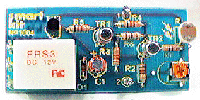
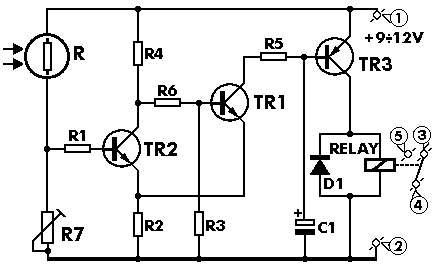
After finishing your work cut off the excess of the component leads and clean the board thoroughly with a suitable solvent to remove all flux residues that still remain on it. You shouldn't face any special problems with this project. The only unusual component is the LDR and you should decide where you want to put your project and how you are going to activate it as it will be necessary to leave a hole in the case for the sensor and possibly orientated the whole case towards the light beam. As usual start building the circuit with the resistors leaving the LDR for the final stage. Mount the relay on the board and solder the transistors and the diode in their places making sure that nothing went in the wrong place or the wrong way round. When everything is in its place solder the LDR carefully, as it is very fragile and can be easily damaged if overheated. Make the last visual check and if you are satisfied that all is well you can connect the circuit to a power supply or a battery of at least 9 VDC. Cover the sensitive surface of the LDR and turn the trimmer till you hear the relay clicking. If you uncover the sensor the relay should click again. You will probably have to read just the trimmer once the circuit is cased and you are ready to use it in some application, in order to fine-tune it to the conditions that you want it to operate in.