In this application, we are building a gaincard like amplifier. This application type is named gainclone in the audio world. To take a satisfactory audio response, we are adding a Linkwitz equaliser to the feedback line and adding bass compensation also.
We are using LM3886 which is the revised version of its brother LM3875.Briefly features of LM3886 are; Maximum Output Power: 68W RMS – 108W Peak
THD: %0.03 at 60W
SNR: 110dB at 60 W – 92.5dB at 1W
PSRR: 120dB
Protection Circuitries: DC/AC Short circuit protection and thermal protection
Output Class: Conjugate AB-A These are the parameters that we are interested in. Honestly this values are much more better than many of HI-FI amplifiers sold in the market. Especially it is hard to find 110dB signal to noise ratio. And another property is, when there is no input, this amplifier is quite like a dead. It is nearly impossible to hear any noise when you stick your ear to the speakers. The circuit below is the recommended design by National Semiconductors engineers. As you can see it is a plain and applicable circuit. Essentially we did any change to the input line hence we didn’t add extra noise. Rin is input level potentiometer, Rb is current limiter potentiometer and Rf1-Ri are gain resistors. In this application, gain is 20k/1k=20 (26.4dB). 22uF capacitor provides the gain curve start from about 7 Hz so it filters unwanted low frequencies.
 This is our design. As you can see, negative feedback line is revised. In this way, about 7dB is gained at 30Hz-70Hz band, and reached about 34db at peak point at 30Hz.
When 26v DC supply is applied to the given design, with 4 ohm speaker load and 2Vp-p input signal it gives about 65W RMS power. For users who want to use 8 ohm, we recommend +/- 38V voltage supply. Of course less than this value may be applied too. Supply circuit is shown below, It is simple too. There are two KBU series (6A) bridge diodes and 2×10000 uF capacitors. As a general rule, 2200uF stabilization capacitor is used per ampere but we are used to use 4700uF per ampere. In our circuit, 2 Amperes will be drawn per line and we use 10000uF capacitors. We recommend you to use 2×10000uF capacitors per each line if you will use the amplifier in party mode.
 Generally in HI-FI applications, toroid transformers are used. But this kind of transformers are expensive and large in volume. Advantage of this transformers is they have very low leakage magnetic flux so they can be placed in the same box with amplifier. But we choose to place transformer and amplifier in separate boxes so we are using standard transformers. Transformer values should be; For 8 Ohm – standard mode : 220 / 2 × 24v (with middle out) at least 250W
For 8 Ohm – part mode: 220 / 2 × 24V (with middle out) at least 350W
For 4 Ohm – standard mode: 220 / 2 × 18v (with middle out) at least 250W
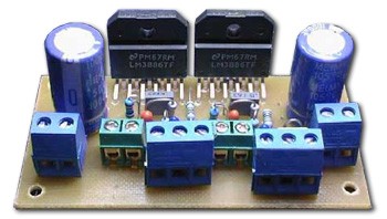
For 4 Ohm – party mode: 220 / 2 × 18v (with middle out) at least 350W As you can see PCB components are tight but as a result it is compact ,small and noise free. Especially short negative feedback line supports this function.
PCB, Layout, Connection Diagram Files |


