| Statistics |
Total online: 1 Guests: 1 Users: 0 |
|
 | |  |
| | Home » Microcontroller » PIC18F2550 Project Board
11:21 PIC18F2550 Project Board |
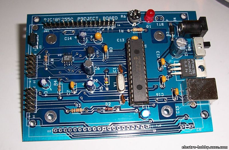
The new PIC18F2550 Project Board was designed as the development platform for student projects.
The board features
MCU: PIC18F2550 with external xtal,
ADC: one channel 0-2.5V sigma-delta converter, Linear Technology LTC2400/LTC2420,
6-channal 10-bit ADC 0-5V,
Display: Two connectors for text LCD or GLCD,
USB: onchip USB port with type B connector,
Power supply: onboard low dropout regulator, rechargeable battery,
Code programming: 10-pin header for In Circuit Loader.
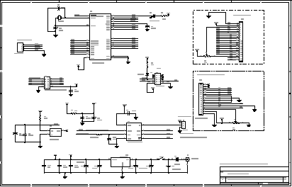
Hardware
The MCU is 28-pin PIC18F2550 with external xtal as the option. We can use internal oscillator. The loader uses only three pins, PGD, PGC and MCLR. J1 is ICSP header, we can plug it to the application board for both code loading and running. The user I/O ports is 6-channel analog input RA0-RA5. PORTB, RB0-RB7 is for LCD interface. User can choose either text LCD at JR1 connector or GLCD at JF1 connector. PORTC, RC0-RC2 is used to interface the LTC2400/LTC2420 SPI bus, sigma delta converter. RC4 and RC5 is USB port signal. RC6 is also available at J2. RC7 is debug LED. J1 is ICSP header. D2 protects VCC from high voltage programming at MCLR pin. U2 can be 20-bit or 24-bit resolution, sigma-delta converter, LTC2420 or LTC2400. J3 is jumper for selecting rejection of the common mode noise frequency, 50Hz or 60Hz. The reference voltage, +2.5V is generated by U3 LM336. The board can be powered by rechargeable battery, BT1.
|
|
Category: Microcontroller |
Views: 2496 |
|
| |
 | |  |
|
|
| |