
| Statistics |
Total online: 1 Guests: 1 Users: 0 |
|
 | |  |
| | Home » Microcontroller » PIC-2 USB Burner
|
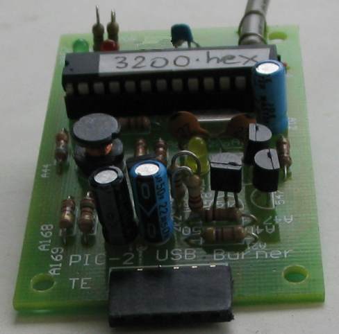
This project is a clone of PICkit-2, (the most successful and cheapest PIC programmer on the market). But PICkit-2 is being phased out and will not be available in the near future. The replacement is more expensive and has less features!
The PIC18F2550 is a specially-designed chip that interfaces to the USB port and handles data from your computer to the chip your are burning, as well as data from the chip on the "Burner Board" to the computer. This saves the need for any other chips in the burner project. The 20MHz crystal must be 20MHz as the chip must handshake, at the correct speed, with the program on the computer.
The only other requirement is to generate approx 13.5v to open up a chip, so it can be read and programmed. Some chips require slightly less than 13v but some need nearly 14v.
This is done via the fourth transistor in the circuit. It receives a waveform from the PIC18F2550 to turn it ON for a short time then it is turned OFF. This action delivers a brief pulse of current through the 1mH inductor and when the transistor is turned off, the inductor produces a high voltage. This voltage is stored in the 22u electrolytic and appears across a voltage divider made up of a 6k8 and 3k3. The chip detects the voltage at the join of the two resistors to maintain a constant 13.5v
This voltage is passed to the chip being programmed by the first three transistors.
The heart of the circuit is a PIC chip. This chip is pre-programmed in the kit because you need a programmer to program it! It's a "Catch-22" situation or a "Chicken-and-the-egg. You need a programmer to program the chip so you can program chips.
If you have one of our other programmers, you can burn a PIC18F2550 and build this project.
To program a PIC18F2550 you will need firmware for PICKIT2
 The project has 3 LEDs. The green and red LEDs connect to the incoming Data+ and Data- lines of the USB port and show when signals are present on these lines. These LEDs show activity and do not have any special importance. They show when PICkit 2 Programmer software is installed and when your laptop recognises the PIC-2 USB Burner.
The yellow LED has three features.
It is the high-speed rectifying diode in the voltage-pump section and allows the positive portions of the high-voltage pulses from the 1mH inductor to pass to the "accumulator section" where a 22u stores the high voltage. Two resistors in a voltage-divider network tap this voltage and send it to a pin on the chip, where the chip controls the pulses sent to the oscillator transistor. When this voltage is 3.6v the voltage at the top of the divider is about 13v.
In idle mode, the yellow LED detects 5v and it illuminates at a very low level.
When the programmer is activated, it "opens-up" the chip you are programming by supplying 13v to the programming pin and reads the type-number of the chip.
The yellow LED will flash very brightly when doing this.
The yellow LED also indicates at high brightness when the programmer is burning a chip.
Parts List
1 - 22R resistor 1/4watt
3 - 100R
3 - 470R
1 - 2k2
1 - 3k3
1 - 6k8
5 - 10k
1 - 100k
2 - 27p ceramics
1 - 100n monoblock
1 - 2u2 16v electrolytic
1 - 22u 16v electrolytic
1 - 47u 16v electrolytic1 - 3mm red LED
1 - 3mm green LED
1 - 3mm orange LED
3 - BC 547 transistors
1 - BC 557 transistor
1 - 1mH choke
1 - 20MHz crystal
1 - 28 pin IC socket
1 - USB plug on 30cm lead
6cm tinned copper wire
30cm very fine solder
1 - PIC18F2550 chip
|
|
Category: Microcontroller |
Views: 2490 |
|
| |
 | |  |
|
|
| |


