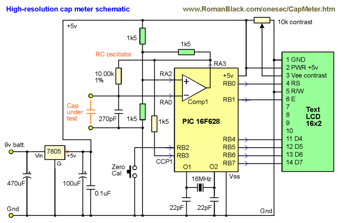
The three 1k5 resistors (green) set the threshold voltages at 1/3Vdd and 2/3Vdd when the comparator output switches. (The PIC is a better comparator than many dedicated comaprator ICs as its output has good push-pull low-Rds FETs).
The oscillation period (freq) is set entirely by RT and CT. RT is a 1% metal film resistor which I measured on my multimeter at 10.00 kohm. Now the only thing that sets the oscillation period is the test cap CT.
The final stage is the PIC timer, that measures the oscillation period very precisely compared to the PICs xtal. And a math calc is done to scale the period to capacitance in farads.
Precision period measuring!
The PIC measures the RC oscillation period by using the PIC's internal hardware capture (CCP1). The PIC xtal is 16MHz so the PIC timer runs at 4MHz.
It adds consecutive captured periods until there is a total accumulated time greater than 2 million counts (>0.5 second). The only error can be the edge error for the first and last capture, so the error is limited to 1 part in 2 million at each end, a total possible error of 1 PPM (1 Part Per Million).
Now it has a precise captured total of periods the average period is determined by dividing the total period with the number of periods captured. As the total is always just over 2 million it is scaled up to 2 billion before the division, to give a lot of accurate decimal digits after the division.
For example;
"10nF" cap, oscillates about 435Hz
218 consecutive periods are captured, a total of 2004597 counts
Math; (2004597*1000)/218 = 2004597000/218 = 9195399
(so the average period is 9195.399 counts)
A second process is used to convert that result to picofarads;
(9195399*100)/scale = 919539900/919 = 1000587
1000587 is then displayed as; 10005.87 pF
Another small cap example;
"100pF" osc about 43500 Hz
21751 periods are captured, a total of 2000091 counts
Math; 2000091000/21751 = 91953
Scaling; 91953000/919 = 100057
100057 is truncated and displayed as 100.05 pF
All the math and scaling systems have been chosen to give the best precision possible from the 32bit unsigned long variables used in the firmware, without resorting to float or 64bit variables that would have needed a larger and more expensive PIC.

If you don't have a 1% metal film 10k resistor (or want to adjust it for high precision) then replace the 10.00k resistor with a resistor and trimpot and then adjust the trimpot to equal 10.00k or to match a precision test capacitor. NOTE! You should also use 1% resistors for the 1k5 resistors for best results!
As the circuit is VERY simple (it's just a PIC and a few parts) I made it on veroboard (stripboard). It is really not worth etching a PCB for this project! A small SMD 5v regulator is soldered to the bottom of the PCB, all the other parts can be seen below;
Download hex code


