The voltage across a capacitor (Vc) being charged by a voltage (V) is Vc = V*(1-e-t/rc). If V, Vc and C are held constant, then the time, 't' will vary in direct proportion to 'r'. Since the threshold voltage for a 1 value in the AVR processor is well defined and and a ratio of the supply voltage we can use it to measure R with a simple R/C timing сircuit.
R-C Time Math
Although I chose a .01uf capacitor mainly because it was what I had in my junk box, It turned out to be a good choice to give a maximum R-C time of less than 1ms. By re-arranging the formula, above, the timing is T = -Ln(.55)RC which gives ~.7ms with .01uf capacitor and 100k + 10k resistor (refer to schematic). Below is the algebra needed to convert the formula for voltage vs. time, to time for a given voltage, resistance and capacitance.
Vc = V(1-e-t/rc)
Vc/V = 1-e-t/rc
Vc/V-1 = -e-t/rc
1-Vc/V = e-t/rc
Ln(1-Vc/V) = -T/RC
Ln(1-Vc/V)RC = -T
-Ln(1-Vc/V)RC = T
Substitute in 1 for V and .45 for Vc (the threshold voltage as a fraction of V) to get:
-Ln(.55)RC = T
This formula can be used to calculate R-C timing circuits for any AVR processor since they all have the same I/O structure and thresholds.
Calibrating the unit
The time needed to charge the capacitors is proportional to the resistance and the capacitance. Both joystick resistors and capacitor values are not precise and the unit needs to adjust the internal math to transform the measured R-C time to the 1.0 to 2.0 ms R/C pulse time. Once calibrated, however, the resulting pulses are precise (limited by the precision of the crystal driving the CPU - usually .1% for ceramic resonator, or .01% for a crystal). The calibration algorithm is fairly trivial. Calibration is a three step process. The first two steps occur when the CAL button is pressed and released:
Stop generating R/C pulses, clear LCD and display "CALIBRATE", Record current R-C timing as the initial minimum and maximum value.
Start scanning the inputs, recording the maximum and minimum values measured.
The third step occurs when the CAL button is pushed the second time.
The center position is calculated as 1/2 the distance between the minimum and maximum values. Then the gain is calculated as 1000 * 16 / (maximum - minimum). Both the center and gain are then recorded in non-volatile EEPROM memory.
The output range is 1000 us (1.0ms to 2.0ms). To preserve accuracy, I multiplied that by 16 and divided by the count, in uS, for the R-C timing. When computing the output value, I multiply the R-C time by the gain, divide by 16 (right shift four bits) and add 1000 to get the 1.000 to 2.000ms pulse. This is an example of using fixed point binary fractions. In this case the gain is a 12.4 binary number, which fits conveniently in a 16 bit word.
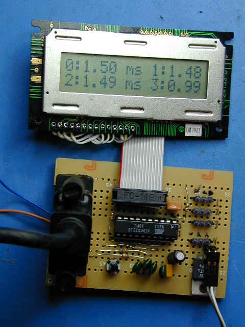
The LCD display
LCD display is an industry standard HD44780 compatible character display. These displays are readily available, surplus, for $4-15 dollars in 1x8 to 4x40 character formats. All the displays have a 14 pin connector, either as an in-line or dual 2x7, header. All displays can be operated in an 8 bit or 4 bit I/O mode. The code implements a four bit interface requiring 6 I/O lines of the processor. It is a little more work to use the 4 bit mode, but the payoff is saving 4 I/O lines on your processor. There are other tricks to interfacing an LCD with as little as one line, but these all require an additional chip and even more code.
Normally LCD code reads a register in the display to determine when it is ready for the next command. By using long enough delays, the LCD driver can dispense with this step, save one I/O line and also keep on working when the LCD is disconnected. There are lots of web sites devoted to LCD interface techniques.
The schematic the connection between the CPU and the LCD. There is a small potentiometer to adjust the contrast of the display. You can tie the contrast pin (3) to ground and usually the contrast is sufficient. That is what I did on the prototype. The interface to the LCD is defined in the file lcd.inc in the source code. You need to specify the port that the data is on and whether it is high or low nibble. You also need to specify the port and bits that the control lines are assigned.
The code is a zip file containing source, makefile and copyright information. You need the latest AVR-GCC compiler from www.avrfreaks.net (GCC 3.2 experimental) to compile the code. The resulting .HEX file can be loaded into an Atmel AT90S2313 processor. By changing the processor type in the makefile you can run this code in any 8 mhz part with 15 or more I/O pins. Simple changes in the code will accommodate up to 8 inputs and outputs for an expanded pulse generator, or, if you used one of the tiny AVR parts, you could make a single or dual channel generator with an 8 pin part.
Download Source Code