
| Statistics |
Total online: 1 Guests: 1 Users: 0 |
|
 | |  |
| | Home » Audio » Stereo audio amplifier with digital volume control
22:24 Stereo audio amplifier with digital volume control |
Perhaps you would know how to make a stereo audio amplifier using two LM386 ICs. But do you know how to add the digital volume control feature to it? If not, check this project. It uses a DS1868 digital potentiometer that creates a voltage divider network at the input stage of LM386 to control the fraction of signal fed to the amplifier. The potentiometer wiper position is varied digitally by a PIC microcontroller based on the user inputs.
This project uses MAXIM’s DS1868 dual digital potentiometer chip and a PIC microcontroller with the two LM386 ICs to control the volume of the stereo outputs.
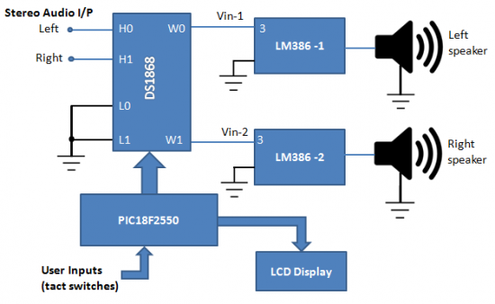
The block diagram below shows the operation of the stereo audio amplifier with separate volume control for left and right speakers. The DS1868 has two potentiometers and therefore a single chip is enough for two LM386 circuits. The DS1868 is offered in three standard resistance values: 10, 50, and 100 KΩ versions. I am using DS1868-010, which is the 10K version. The stereo audio is fed to the high ends (H0 and H1) of the two potentiometers, while both the low ends are grounded. The input audio signals for the two LM386 stages are derived from the wiper terminals (W0 and W1). The PIC18F2550 microcontroller receives user inputs from tact switches and set the wiper positions accordingly, which in fact control the output volume. A LCD is used to display the individual channel volume level.
 Circuit Diagram The block diagram provided in the the theory section described how this project works. The stereo audio amplification circuit is made up of two LM386 mono amplifiers. The circuit diagram of LM386 based mono amplifier was also described above. The microcontroller, DS1868 digital potentiometer, LCD and tact switches connections are shown below.
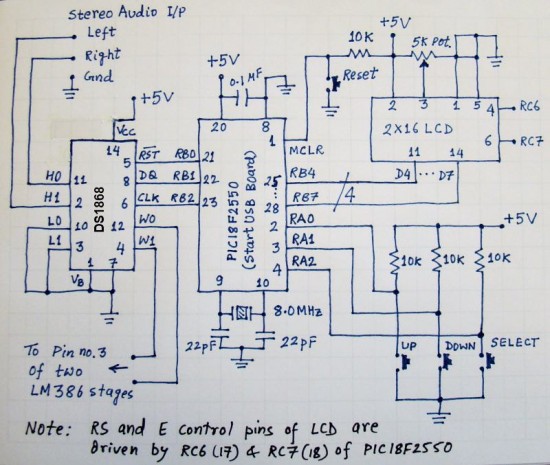 There are three tact switches for user inputs. They are named UP, DOWN, and SELECT in the circuit diagram. UP is to increase and DOWN is to decrease the volume. With the SELECT input, you can set the volume of left and right speakers jointly or individually. As mentioned earlier too, the stereo input is fed to the H0 and H1 pins of DS1868, whereas the L0 and L1 pins are grounded. The two wiper terminals, W0 and W1, are connected to the input pins of the two LM386 mono amplifiers. The LCD is operated in 4-bit mode and the data pins (D4-D7) are connected to RB4 through RB7 port pins. The two LCD control pins, RS and E, are driven by RC6 and RC7 pins of PIC18F2550.
Software The firmware for PIC is developed in mikroC Pro for PIC compiler. It’s a test version where I have set 10 volume levels from 0 to maximum, with the step size of 25 for the potentiometer wiper position. But you can further reduce the step size, say to 5. That will give you 51 discrete volume steps from 0 to maximum. Every time you press UP or DOWN button, the output volume will go increase or decrease with a constant amount, which corresponds to the step size. You can select individual or both channels (left and right speakers) for UP and DOWN operations. Download the source code and HEX file for this project
|
|
Category: Audio |
Views: 4847 |
|
| |
 | |  |
|
|
| |


