
| Statistics |
Total online: 1 Guests: 1 Users: 0 |
|
 | |  |
| | Home » Radio Frequency » Super Scanner 45-860MHz with 0.01Hz stepsize
14:37 Super Scanner 45-860MHz with 0.01Hz stepsize |
 The project tries to reuse a tuner in order to create a TV receiver with 45-860MHz super scanner and a step size of 0.01Hz. The project tries to reuse a tuner in order to create a TV receiver with 45-860MHz super scanner and a step size of 0.01Hz.
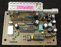
A digital type of TV or VCR tuner is the heart of this receiver wherein through the I2C interface, the received frequency is programmed into the tuner. A second mixer using DDS as oscillator was added because the smallest step size of a tuner is 31.25kHz, 50kHz, or 62.5kHz, which is too wide for narrow band signals. This DDS configuration can perform the smallest step size of 0.01Hz. The input frequency is set to tree bands:VLF 48-180MHz  VHF 160-470MHzUHF430-860MHz VHF 160-470MHzUHF430-860MHzhe analogue tuners use an input voltage 0-28V to control the tuner VCO (Voltage Controlled Oscillator) and there is also 3 pin to select band (see fig at right). The tuning voltage also control the input filter to the tuner. The input RF is mixed with the VCO signal and the output product (IF) is set to 38.9MHz. The disadvantage of the analogue tuner is that it is difficult to get stable tuning voltage to the VCO and to know wich frequency you are receiving. The digital tuner works in another way, they use a PLL synthesizer circuit to set the frequency. The synthesizer can be programmed to any frequency in the range of 45 to 860MHz. The synthesizer sens the frequency from the tuner VCO and compare it with the programmed frequency. The circuit will then regulated the tuning voltage until the frequency from the VCO and the programmed are in phase with eachother. The bands and the frequency is programmed by an I2C interface. The digital tuner is very exact in frequency and is very stable. The only disadvantage with this type of tuner is that you need digital logic to program the tuner. I usually use a PIC controller to program my digital tuners.Lets have a look at some tuners: UV916 and a noname tunerIn most cases you will have difficult to see the lable of the tuner or even find a lable. I don't know why they are so lousy to identify the tuners. I have collected over 50 tuners from different TV and VCR and I have manage to find about 10 with proper lable. Don't worry yet! Even if you wont find any info about the tuner you can open it and identify the circuits. Most often you will find a PLL synthesizer and one demodulator/mixer circuit. Try to find the datasheets over the PLL and you will understand how to program the tuner. One common tuner is UV916. The photo below is a UV916H /UV916 E tuner. I will help you to identify all parts: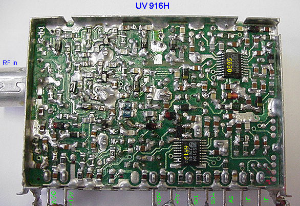
This tuner is based on two circuits. TDA5630 "9 V VHF, hyperband and UHF mixer/oscillator for TV and VCR 3-band tuners" and TSA5512 "1.3 GHz Bidirectional I2C-buscontrolled synthesizer".
The TSA5512 circuit is digitally programmed to a desired frequency and the PLL set the Vtuning voltage to the TDA5630 ciruit.
The stepsize of this tuner is fixed to 62.5kHz. This tuner has 9 input and a shield (shield=ground).
AGC = Automatic Gain Control. Apply a voltage 0 to 12V will set the gain of the preamplifier.
+ 12V = Powersupply to the preamplifier and the TDA5630 circuit.
+ 33V = Powersupply to the PLL tuning system.
+ 5V = Powersupply to the PLL synthesizer.
SCL = I2C clock to the PLL synthesizer.
SDA = I2C data to the PLL synthesizer.
AS = Adress selection for the tuner (Are used with MA1 and MA0 see page 8 datasheets)
IF = IF out
IF = IF out
One tricky thing with tuners is to set the desired band. The band are selected by programing the port register P0 to P7 in the TSA5512 circuit. The UV916 band is following:
| BAND | P7 | P6 | P5 | P4 | P3 | P2 | P1 | P0 | | LOW BAND (60h) | 0 | 1 | 1 | 0 | 0 | X | X | X | | MID BAND (50h) | 0 | 1 | 0 | 1 | 0 | X | X | X | | HIGH BAND (30h) | 0 | 0 | 1 | 1 | 0 | X | X | X |
No name tuner
Now, lets try to identify the part in a noname tuner I have found. After removing the cover we find two circuits.
TDA 5630 is the mixer and VCO, the TSA5522 is the PLL synthesizer.
If we look into the datasheets for the TSA5522 we will find lot of valuable information. With the datasheeets and by following the strip line of the PCB we can identify the SCL and SDA input. We will also find a pin called P6 which is an input to a 5 level ADC converter which can be used to apply AFC (Automatic Frequency Control) information to the microcontroller. In most cases, you will not use this input and can therefor leave it floating. You will also find a input called AS. By applying a specific voltage to this input you can select several synthesizers (up to 3) in one system. In most cases you will only use one tuner, so you can leave this input floating(set MA1=0 and MA2=1 always valid). The PLL circuit use 5V DC and this input is not so difficult to find. IF you look at page 13 in the datasheets you will see how the PLL works. The PLL use + 33V DC and the pin CP will set the Vtune. By following the strip line in the PCB I find the +33V DC input.
If we now look into the datasheets for the TDA5630 we find it is using +9V DC and this voltage is found at pin 5 which guids me to the input pin. The last pin can not be found in any datashets and that pin is called AGC input (automatic Gain Control). This pin control the gain of a preamplifier. The input voltage to the AGC will set the gain. A good guidline is to set this input to half the voltage of the system, which would be +6V by two resistor in serie. Most often you will find the ACG input as the first pin closest to the RF input side. input pin. The last pin can not be found in any datashets and that pin is called AGC input (automatic Gain Control). This pin control the gain of a preamplifier. The input voltage to the AGC will set the gain. A good guidline is to set this input to half the voltage of the system, which would be +6V by two resistor in serie. Most often you will find the ACG input as the first pin closest to the RF input side.
Now we have identified all input to this unknown tuner. Look into the datasheets to examine and understand the register in the PLL synthesizer circuit TSA5522.
Block diagram of the Super Receiver
Don't be scared of all filters and mixers, in a few minutes you will understand each of them. The tuner is digital type where the frequency can be controlled via I2C inteface. The smallest frequency step size of the tuner is 62.5 kHz. This stepsize is often to large. The standard stepsize in scanners are 50kHz, 25kHz, 12.5 kHz, and 5kHz and less. In this construction I will let the tuner make the large step in frequency (62.5kHz) and then I will let a DDS controlled osc make the fine step inside the 62.5kHz.
You can think of it like the fig at right:
You have two knobs. The left (red) is the tuner which can step in 62.5kHz. The right one is the DDS which can step from 0 to 62.49999kHz in 0.011Hz step if you want.In the example I have set the resolution to 1Hz, so the DDS step to 62.499kHz. The formula at bottom of the figure show you how you can set the two knobs to get all wanted frequencies.(In reallity the DDS freq is not from 0 to 62.499kHz it is 5.01375MHz to 5.07625MHz).
With this two unit (tuner and DDS) you will now be able to scann the complete tuner range from 45-860MHz in 0.011Hz step! To understand this tuner I will explain each block. The output IF (intermediate Frequency) from the tuner is set to 37 MHz (european standard). A sharp filter (SAW) reject all other frequencies. The signal go to the first mixer where it Is mixed with a constant frequency from a crystal oscillator at 42.5 MHz.
The output product from the first mixer will be 42.5 - 37.0 = 5.5MHz. I use a standard 5.5MHz ceramic filter to filter the signal and reject all other frequencies. This filter should have 100kHz bandwith which is common in TV and VCR.
Before we look at mixer 2 we will go to the final block which is the demodulator. The demodulator works at 455kHz and before the demodulator you can find a 455kHz ceramic filter. If we lock the DDS frequency to 5.5MHz - 455kHz = 5.045MHz, we will receive exact at the frequency which the tuner is set to. Remember I told you the smallest tuner step is 62.5kHz.
For the UV916 the stepsize is fixed to 62.5kHz!
Now, If we change the DDS frequency ±31.25kHz we will be able to use the DDS for finetuning.
The DDS frequency will be be 5.045MHz ±31.25kHz.
HARDWARE and Schematic
Tuner section
In this project I used the commonly used tuner UV916. The AGC is set to +6V via 2 resistors. I have 3 different power supply to the unit(+5, +12 and +33V). The I2C (SCL, SDA) interface is connected to the PIC (RB3 and RB4). P3 is left open and the IF output (37.0MHz) is connected to the SAW filter. The filter has 2 inputs and two outputs. The outputs are connected to the radio circuit. The saw filter is a passband filter from 34-38.9MHz. It will help to remove the mirror frequency.
DDS section
The DDS is clocked by a 50MHz crystall module.The PIC program the DDS via RB5, RB6 and RB7). L1 and L2 filter the powersupply to the circuit and separate the analogue and the digital power supply. The output from the DDS is connected to a 300 ohm resistor and after the resistor is the 9 pole filter. This filter is to suppress overtones and glitches from the digital part in the circuit. After the filter you will have a nice shaped periodic signal at 5.045MHz.
One difficult is that the circuit is a fine pitch circuit, so you must have a sharp soldering tool. Don't be upset when you solder this tiny thing.....
Radio receiver circuit
The circuit is a MC13136. At pin 1 and 2 is the oscillator. I use a crystall controlled configuration. At pin 3 you will find an output buffer from the osc. The signal from the tuner passes the SAW filter and into mixer 1 via pin 22. The product from this mixer can be found at pin 20. A 5.5MHz ceramic filter damp all other frequency than 5.5MHz +/- 100kHz. The signal enter mixer 2. At this mixer the signal is mixed with the DDS frequency at pin 6. The product passes a 455kHz ceramic filter and into the FM demodulator. The FM demodulator use a quad coil (pin 13) to demodulate the audio signal. The RSSI Relative Signal Strength Indicator (pin 15-16) will give you a voltage level prortional to the signal trength in dBm. If you use this unit as a spectrum analyzer you can use this output to plot the Y-axle. The X-axle is the frequency. At pin 17 you will find the audio output. It is a low level signal about 50-150mV. I amplify this signal in a simple audio amplifier at the bottom of the schematic.
RS232 communication:
 I will now explain how the communication between the computer and the Super-tuner works. You don't need to understand this if you don't want, but some people may want to make own controlling program for the super-tuner. The program I have made takes care of everything! I will now explain how the communication between the computer and the Super-tuner works. You don't need to understand this if you don't want, but some people may want to make own controlling program for the super-tuner. The program I have made takes care of everything!
I have constructed this project so that you must use a computer to set the frequency. In this way you can easally make sure it works and from there you can add display and buttons etc. Finally you might end up with a portable self working unit. But first you need to make sure it works and the easiest way is to let a computer calculate and set the tuner and DDS for proper frequency. To make a computer able to communicate with the unit you need a RS232 to TTL converter which the MAX232 circuit does. I use 19200 baud,even parity,8 bit and 1 star and 1 stop bit (19200,e,8,1). I will now explain the communication protocol.
The software I have made is general. It means you can use many different tuner with this software. There is totally 9 register which must be set before you can receive anything. The Adressbyte is to set the tuneradress for I2C. Dividerbyte 1 and 2 is to set the frequency in the tuner. The Controlbyte controls PLL currents and other stuff, Portbytes set the acutal receiving band. For more details look into the datasheets over the circuit TSA5512.pdf and you will see every detail of the tuner registers. What the software does is to calculate the content of the 9 registers and send 9 byte to the PIC. The PIC receive the data and convert it to I2C which will program the tuner and serial data for the DDS. You don't have to consider what the PIC does, but it can bee good to understand what happens betwen the computer and the PIC if you want to write your own computer program to control the receiver.
Windows Software
I have made a simple window software to control this Super-Receiver. The pic below show the software.
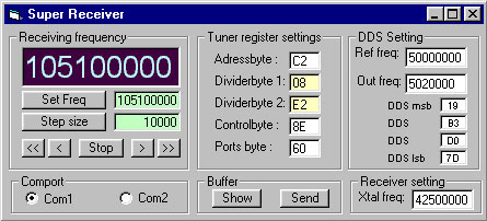
Download Software for WindowsI will now explain the different windows:Receiving FrequencyReceiving Frequency is where you can set the frequency you want to receive. You enter a value in the green filed and press Set Freq. You can also set the step size for scanning up/down. The stepsize is entered in the same way as the frequency. ComportIn this window you can select wich port you use to the Super Tuner.Tuner register settingsIn this window you can set the register in the tuner. There is two yellow areas which is set automatically and that is Dividerbyte 1 and Dividerbyte 2. These two registers is calculated from the frequency you have entered.Adressbyte, Controlbyte and Ports byte can be entered any time. When you change a value of any of these registers the software will automatically send info to uppdate the tuner.Remember to change band (Ports byte) manually when you tune over 150MHz and over 450MHz. The software will not do this automatically!DDS SettingThe DDS need to know the Reference frequency to the DDS. The output frequency is calculated from the receiving frequency you have entered earlier. You will also see the 32 bit divider bits in the DDS, displayed as four bytes. BufferThe buffers shows the 9 byte which will be sent to the PIC. By pressing send you will send the buffer to the PIC over RS232 line. When ever you change a value the buffer will be sent automatically to the PIC.Let's see if the numbers above is correct, shall we!IF = Xtal - DDS - 455kHz => 42.5e6 - 5.02e6 - 455e3 = 37.025.000 HzTuner VCO = 62500 * tuner divider => 62500 * 2274 =142.125.000 HzRF receive = Tuner VCO - IF => 142.125e6 -37.025.e6 = 105.1 MHzLooking great!That was all about the software!Download source code for PIC16f84
|
|
Category: Radio Frequency |
Views: 15977 |
|
| |
 | |  |
|
|
| |


