 The circuit illustrates a construction of motors with the use of microcontrollers as the primary component. The circuit illustrates a construction of motors with the use of microcontrollers as the primary component.
Electric motors are a key way of converting electrical power (voltage and current) into mechanical power (torque and speed), and because electric motors are simple and reliable machines, they can be found all over, in many different shapes and sizes. Just considering a normal (gasoline-powered) car, there are a great number of electric motors: - the powerful starter motor and alternator
- alternating windshield wiper motors
- intermittent-use power windows and door locks
- the blower fan that moves hot and cold air into the cabin
- the tiny motors inside the CD player
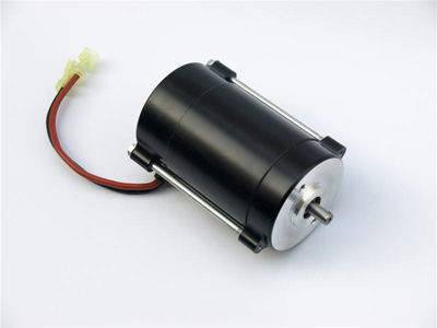
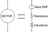
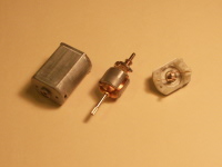
And I'm sure you can think of others. But from an electronics perspective, motors are slightly tricky loads to control -- they're not just a resistor! Even for a single applied voltage, their current varies with loading, starting, and stopping, and the energy stored in the magnetic field of the windings means that they are inductive, which can present a danger to other circuit components if it isn't handled properly. While a full analysis would have to look simultaneously at the motor and the attached mechanical system, in this video tutorial we're just going to address the electrical side of the system. This includes some experiments you should try with a DC motor, a model of the system from an electrical perspective, building a MOSFET-based switching circuit, and finally two demos of a microcontroller-operated motor. This video and webpage specifically addresses a brushed DC motor, and although the specifics are not fully applicable to brushless (BLDC) motors, stepper motors, or AC motors, the big ideas about motor modeling and control will be useful in those areas as well. Here are some photos and drawings related to the video (click to enlarge):
 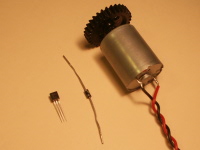 
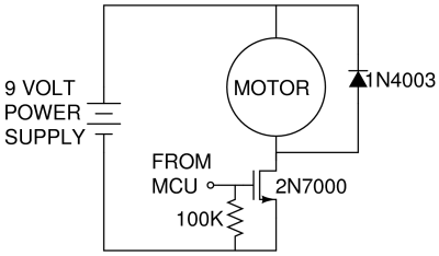
Our final motor control circuit looks like this:
Here is an overview of the nine quick motor experiments / observations made during the video. We highly suggest you try these yourself with a small DC brushed motor to get a better feel for what's going on. - Spinning the motor makes a voltage. This is called the back-EMF (EMF stands for electromotive force, which is just a voltage), and the voltage is proportional to the speed of rotation, and it happens because the permanent magnets are moving relative to the coils of the motor. This is how a permanent magnet motor can be used in reverse as a generator.
- Spinning the motor can light an LED. If an LED is attached and you are able to spin the motor fast enough in one direction to get to the forward voltage of the LED (about 2 volts), the LED will light. You are then turning mechanical energy into electrical energy and then into optical energy as photons.
- Inertia keeps the rotor spinning. A spinning object such as the rotor likes to keep spinning, and is only slowed down by friction.
- When shorted, the rotor is harder to turn. This may seem strange, but if the motor is electrically shorted, it's harder to turn the shaft, because the back-EMF generated by the spinning causes a current to flow. This current produces a torque which opposes the motion of the rotor. (It must be in this direction for energy conservation to work!) Also, the motor no longer spins much after the driving force applied by my hand is released, because its motion is quickly impeded by the motor torque. This experiment may be the least familiar or intuitive to you out of the nine -- give it a try!
- The winding resistance of the motor can be measured. With a multimeter, we can measure the motor resistance, which for our motor was about 9 ohms. But the big idea of this video is that the motor is not just a resistance -- there's other effects going on too, so making decisions only considering the resistive part may lead to trouble.
- The operating current under no load is small. With a multimeter, we measured an operating current of about 0.06 amps when driven from a 9V source, even though the previous measurement of 9 ohms might have suggested 9V/9 ohms = about 1 amp. That's because when the motor is spinning, there's a large back-EMF voltage, so the actual voltage drop across the 9 ohm resistor is much smaller. In this case, it's about (9 ohms)*(0.06 amps)=0.54 volts, which means that only 6% of the power going into the motor is being dissipated in the winding resistance, and the rest is going into friction or electromagnetic losses.
- The current required when starting the motor is larger. When the motor is first started from rest, there's zero back-EMF, so the current is many times larger than the operating current.
- The stall current, when the shaft is locked, is very large. If the motor shaft is physically prevented from spinning, we see the stall current, which is really just the operating voltage divided by the winding resistance. This is the largest current the motor will ever see, and it is an important number to consider when designing the motor control circuit.
- A spark can be seen when the motor is switched on/off. Because energy is stored in the magnetic field due to a current, it's common to see sparks when the motor is switched on/off, because the energy in the magnetic field has to go somewhere when the current stops. Sparks mean high voltages -- hundreds or thousands of volts -- and this can be fatal for other circuit elements like transistors and microcontrollers.
Go give them a try! Particularly for the experiments where current is applied, make sure that you only use a small motor disconnected from any gearing or mechanical loads so you don't hurt yourself.
|


