Parts List
Element Value/Type Case Remarks
R1 100k 1206
R2 100k 1206
R3 10k Potentiometer
R4 30k 1206
R5 10k 1206
R6 10k 1206
R7 7k5 1206
R8 7k5 1206
R9 500R Potentiometer
R10 500R Potentiometer
R11 5k1 1206
C1 - C9 100n 1206
C10 22u/6V SMD A
C11 10n 1206 Optional element - protect Q1 against voltage peek after switch off fan. Most of the computer type fans which I tested didn't produce voltage peeks dangerous for Q1
C12 10u/50V
L1 47u 1210 Do Not Assemble - cross PCB pads
D1 DIODE SMD A Optional element - protect Q1 against voltage peek after switch off fan. Most of the computer type fans which I tested didn't produce voltage peeks dangerous for Q1
D2 DIODE SMD A e.g. SK310A
U1 7805 TO-252 Voltage regulator +5V, e.g. LM7805
U2 7812 TO220 Voltage regulator +12V, e.g. LM7812
U3 ATMEGA8 TQFP32
LCD GOLDPIN 1x16
J1 GOLDPIN 1x2 FAN_CON - fan connector
J2 GOLDPIN 1x1 +12V_CON - optional +12V supply connector
J3 GOLDPIN 1x1 +35V_CON - main supply connector
J4 GOLDPIN 1x3 ground and measured signals
S1 SWITCH
Q1 MOSFET N SOT-23 e.g. BSS-138 (fan current lees than 200mA)
| ELEMENT | ACTION |
| S1 | Setup button
When pushing this button the shunt resistor value appears. If the resistor value is known, repeat button pushing until correct value reached. If resistor value is unknown (e.g. self made resistor), short PSU output by ammeter, set some current by PSU current limit regulator and then, push button, lead to equal current indication on ammeter and multimeter.
After resistor value setup, button must not be pressed for about 5 seconds. The next parameter to set up is fan switch-on power threshold. It is not the real power loosed on output transistor (transistors), because multimeter has information on voltage drop on transistor and driving current. To avoid instability switch-off threshold is automatically set to 20% less than switch-on one. |
| R9 | Fine voltage circuit regulation potentiometer.
To reduce ADC conversion errors like un-linearity, gain factor etc. measuring range is divided into two sub-ranges 0-10V and 10-30V (switch threshold can be between 7-13V depend on sourcing current and elements tolerance).
To regulate fine sub-range connect voltmeter to PSU output, set up voltage at about 9V and turn R9 until voltmeter and multimeter indications are equal. |
| R10 | Coarse voltage circuit regulation potentiometer..
There is over-sampling applied in multimeter software, so measuring resolution is the same in fine and coarse circuit and is 10mV. Because of the reason described above multimeter has two measuring circuits.
To regulate coarse sub-range connect voltmeter to PSU output, set up voltage at about 19V and turn R10 until voltmeter and multimeter indication are equal. (If you posses 4.5 digit voltmeter, you could regulate at voltage 30V) |
| R3 | LCD contrast potentiometer. Turn that potentiometer first, if nothing is visible on LCD. |
| J1 | Fan connector.
Pin no. 1: Fan "+"
Pin no. 2: Fan "-" |
| J2 | +12V
If +12V DC is available in your PSU, connect it to that pin. In that case you shouldn't assemble +12V voltage regulator U2 on PCB.
That solution is convenient for multimeter, because eliminates U2 heating and permit to connect fan and LCD with higher current consumption.
If you haven't got +12V DC in your PSU, left that pin unconnected. |
| J3 | +35V
Rectifier bridge voltage. See U2 element you used data sheet to know about maximum voltage it can work properly. On the other hand the minimum voltage on that pin mustn't drop bellow c.a. 9V, or 6.5V if low drop type U2 and U3 voltage regulators were used.
That pin should be connected even if +12V DC is connected to J2 pin. Voltage from that pin deliver information for fan switching. |
| J4 | Measuring signal connector.
Multimeter is suitable for voltage and current measurement in PSU, where current sense shunt resistor is connected in series with load and is in negative rail.
Pin no.1: voltage measurement U - connect to "+" PSU output, best directly to output terminal;
Pin no.2: current measurement I - connect to "-" PSU output, best directly to output terminal;
Pin no.3: ground - connect to shunt resistor terminal opposite to that connected to "-" PSU output. |
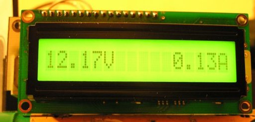
| LCD | LCD connector.
Multimeter works properly with LCD's 1x16 logical controlled as 2x8 (most of LCD's available on the market).
Because of linear voltage regulators used in multimeter, sourcing current is limited. Main current consumption elements are fan and LCD backlight, so:
- use LCD with LED backlight (typically current consumption is less than 15mA);
- use low speed, low current fan. Additional advantage of that solution will be silence. |
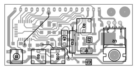
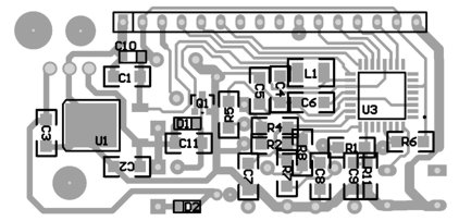
Download .hex filePCB layouts 


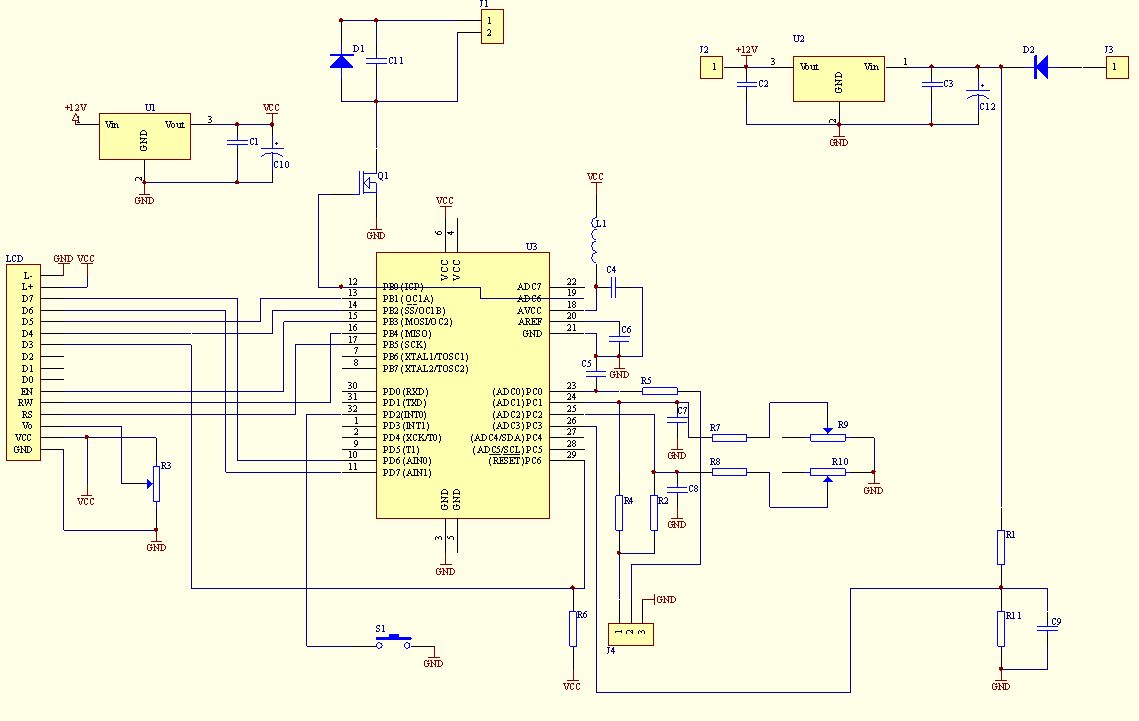
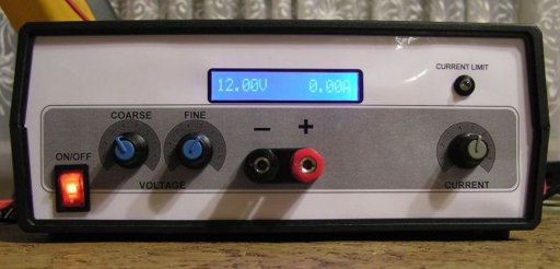 This multimeter was designed to measure output voltage and current in a PSU, where the current sense shunt resistor is connected in series with load at the negative voltage rail. It needs only one supply voltage that can be acquired from main PSU. An additional function of the multimeter is that it can control (switch on and off) an electric fan used to cool the main heatsink. The power threshold at which the fan switches on can be adjusted using One Touch Button Setup.