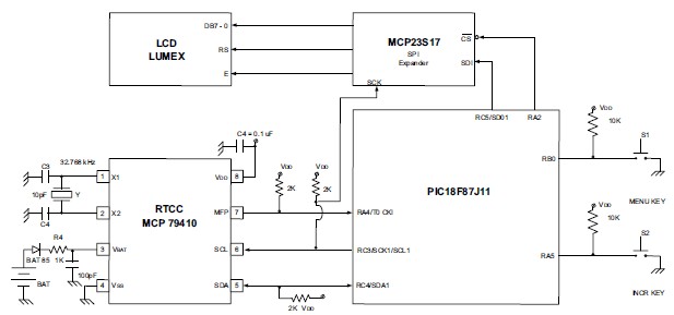
A very simple complete watch system can be designed using the MCP79410 real time clock calendar device . The MCP79410 is a feature-rich RTCC that incorporates EEPROM, SRAM, unique ID and time-stamp. As you can see in the schematic circuit diagram, this simple watch system is based on a PIC18F87J11 controller and some other few external electronic parts . This watch system circuit project was designed by Microchip Technology using a PIC18 Explorer demo board on which is mounted a PIC18F87J11 MCU , but you can design this watch electronic project without using PIC18 Explorer demo board . The MCP79410 is an I2C slave device, working on the related bidirectional 2-wire bus . This circuit will display six time/date variables (year, month, date, hour, minutes, seconds) using the interrupts of the . Setup of the above variables using the two push buttons: S1 = MENU KEY, S2 = INCREMENT KEY. The real-time display of the time/date variables is performed as long as the MENU KEY (S1) is not pressed . Going from one variable to another is performed through the MENU KEY, and incrementing a variable is performed through the INCREMENT KEY. This circuit require a 5 volt DC power supply and a 3-volt battery which sustain the RTCC when VDD is not present. The code is designed by Microchip Technology and is written in ‘C’ using the C18 compiler . |