
| Statistics |
Total online: 1 Guests: 1 Users: 0 |
|
 | |  |
| | Home » Tests and Measurement » 2.5 GHz Frequency Counter with Blue 2x16 LCD display
11:08 2.5 GHz Frequency Counter with Blue 2x16 LCD display |
A frequency counter is one of the most important measuring tool we need as homebrew's of RF electronic. This frequency counter has very high performance and still is very easy to build and to use. Anyone can build it and have a professional frequency measuring tool. The counter is based around a LCD display with 2 lines and 16 chars.
I have used a HD44780 based display which is very common. A PIC16F870 circuit controls all counting and display functions. A prescaler is added to make it possible to measure up to 2.5GHz with high sensitivity.
In the menu system of this frequency counter, you can choose between two reference frequencies.
On-board 13.000MHz crystal (picture at right), orExternal 10.000MHz signal.
The reason of using a external 10.000 MHz reference frequency is because it is common among reference oscillators, as HP Z3801 GPS locked frequency source.
How to add/subtract the IF frequency ?
 Radio receivers today works with an intermediate frequency (IF). There is three frequencies which are often used and they are 455 kHz, 10.7MHz and 21.4MHz. The reason of having a intermediate frequency is to optimise the filtering in a receiver. The picture at right show you the basic principle of a receiver. You have an antenna connected to a mixer and a LC unit (oscillator) which also is connected to same mixer. The product of the mixer will be many different frequencies, but the most interesting are the IF at 10.7 MHz or 455 kHz. Radio receivers today works with an intermediate frequency (IF). There is three frequencies which are often used and they are 455 kHz, 10.7MHz and 21.4MHz. The reason of having a intermediate frequency is to optimise the filtering in a receiver. The picture at right show you the basic principle of a receiver. You have an antenna connected to a mixer and a LC unit (oscillator) which also is connected to same mixer. The product of the mixer will be many different frequencies, but the most interesting are the IF at 10.7 MHz or 455 kHz.
To produce the IF frequency, your oscillator must be running 10.7 MHz above the desired frequency or 10.7 MHz below the desired frequency.
Same if the IF is 455 kHz, then the oscillator must be running 455 kHz above the desired frequency or 455 kHz below the desired frequency.
Example:
You want to receive at 100 MHz. Then the OSC is set 110.7 MHz and that will give you and IF of = 10.7 MHz.
If you now measure the OSC your frequency counter will show 110.7 MHz, but you are listening to 100 MHz!!!
What we want is to (add) or subtract the IF (10.7 MHz) from the measured frequency so you can se the actual receiving frequency.
The software in this counter can handle all that for you. Just hook up the counter with your receiving OSC and enjoy.
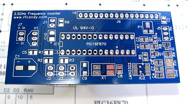
The main part of this project is a LCD, PIC16F870 and a prescaler LMX2322.
The LCD is a standard 2 line 16 chars display connected in 4-wire mode to the PIC.
At the bottom you will find a 13.000 MHz or external 10.000 MHz frequency connected to the PIC.
Capacitor C9 is variable and is used to calibrate the Frequency counter.
If you have an external 10 MHz oscillator you should remove the crystal, C8, C9 and connect the signal to pin 9 of the PIC16F870.
At pin 5 you have an output. It can be connected to a piezo buzzer or equal to generate a beep whenever any button is pressed.
If you don't want to use it, you can leave this pin as it is.
Pin 2 is the switch SW1 which you can toggle choices in the menu system.
Pin 4 is the switch SW2 which guide you through a seven stages menu system.
Schematic
Calibration: When a 13 MHz crystal is used, the calibration of the counter is made by the variable capacitor C9. It will be able to change the timing ±100ppm (±10kHz at 100MHz). Most people has no good reference to calibrate against and then it is a bit difficult. The frequency counter is supposed to be a measuring tool with good accuracy. Download Pcb
Source Code
Frequency Counter Manual
|
|
Category: Tests and Measurement |
Views: 5882 |
|
| |
 | |  |
|
|
| |


